|
General Description
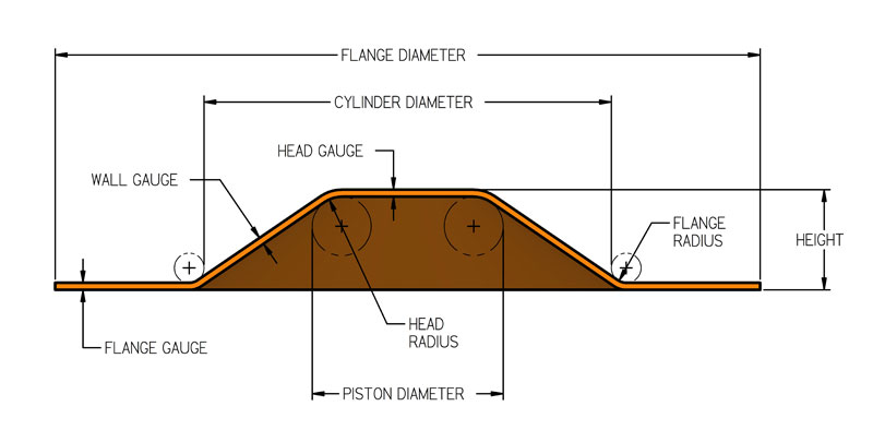
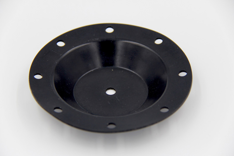
| This
diaphragm type, commonly referred to as dish-shaped, has
a sidewall that slopes gradually from the cylinder to
the piston. This diaphragm is designed to be flexed in
both directions to its full height. It may be double-coated
to take pressure in both directions. Due to its wide convolution
and gradual sidewall slope, the total travel and ability
to withstand high pressures are limited. The effective
pressure also varies through its stroke. |
 |
 |
 |
|
|
Dimensions and Tolerances
|
|
Inches |
mm |
Inches |
mm |
Inches |
mm |
Inches |
mm |
Cylinder Diameter
|
1.00-2.50
|
25-64
|
2.51-4.00
|
64-102
|
4.01-8.00
|
102-205
|
8.01 & up
|
205 & up
|
| Height |
See available sizes table
|
| Cylinder
Diameter |
Tolerances on Cylinder Diameter and Piston Diameter
are ± 0.010" per inch (0.254 mm) of
diameter but the tolerance will be no less than
± 0.010" (0.254 mm), or greater than
± .060" (1.52 mm)
|
| Piston
Diameter |
| Head
& Flange Thickness |
.017 ± .005
|
.43 ± .13
|
.024 ± .005
|
.61 ± .13
|
.035 ± .005
|
.89 ± .13
|
.045 ± .007
|
1.14 ± 0.18
|
| Wall
Gauge |
.017 ± .005
|
.43 ± .13
|
.024 ± .005
|
.61 ± .13
|
.035 ± .005
|
.89 ± .13
|
.045 ± .007
|
1.14 ± 0.18
|
| Flange
Radius |
.063
|
1.60
|
.094
|
2.39
|
.125
|
3.18
|
.125
|
3.18
|
| Flange
Diameter |
Cyl. Diam. + 1.00
|
Cyl. Diam. + 25.40
|
Cyl. Diam. + 1.500
|
Cyl. Diam. + 38.10
|
Cyl. Diam. + 2.00
|
Cyl. Diam. + 50.80
|
Cyl. Diam. + 2.00
|
Cyl. Diam. + 50.80
|
|
Available Sizes
|
DiaCom
Part No, |
Cylinder
Diameter
|
Piston
Diameter
|
Height
|
Gauge
Approx.
|
Convolution
Width
|
Effective
Pressure
Area
|
Maximum
Half-Stroke
|
| (Inches) |
(mm) |
(Inches) |
(mm) |
(Inches) |
(mm) |
(Inches) |
(mm) |
(Inches) |
(mm) |
(Inches) |
* |
(Inches) |
(mm) |
P-106-16
|
1.06
|
27
|
1.00
|
25
|
0.16
|
4
|
.017
|
0.40
|
0.03
|
0.8
|
0.83
|
5.4
|
0.16
|
4.1
|
P-134-39
|
1.34
|
34
|
0.91
|
23
|
0.39
|
10
|
.017
|
0.40
|
0.22
|
5.5
|
0.99
|
6.4
|
0.39
|
9.9
|
P-144-40
|
1.44
|
37
|
0.69
|
18
|
0.40
|
10
|
.010
|
0.30
|
0.38
|
9.5
|
0.89
|
5.7
|
0.40
|
10.2
|
P-206-50
|
2.06
|
52
|
1.06
|
27
|
0.50
|
13
|
.060
|
1.50
|
0.50
|
12.7
|
1.91
|
12.3
|
0.50
|
12.7
|
P-250-50
|
2.50
|
64
|
1.50
|
38
|
0.50
|
13
|
.060
|
1.50
|
0.50
|
12.7
|
3.14
|
20.3
|
0.50
|
12.7
|
P-275-50
|
2.75
|
70
|
1.75
|
44
|
0.50
|
13
|
.060
|
1.50
|
0.50
|
12.7
|
3.97
|
25.6
|
0.50
|
12.7
|
P-275-53
|
2.75
|
70
|
1.75
|
44
|
0.53
|
13
|
.025
|
0.60
|
0.50
|
12.7
|
3.97
|
25.6
|
0.53
|
13.5
|
P-288-37
|
2.88
|
73
|
1.88
|
48
|
0.37
|
9
|
.030
|
0.80
|
0.50
|
12.7
|
4.45
|
28.7
|
0.37
|
9.4
|
P-300-50
|
3.00
|
76
|
2.00
|
51
|
0.50
|
13
|
.060
|
1.50
|
0.50
|
12.7
|
4.91
|
31.7
|
0.50
|
12.7
|
P-325-52
|
3.25
|
83
|
1.77
|
45
|
0.52
|
13
|
.025
|
0.60
|
0.74
|
18.8
|
4.95
|
31.9
|
0.52
|
13.2
|
P-400-57
|
4.00
|
102
|
3.00
|
76
|
0.57
|
14
|
.060
|
1.50
|
0.50
|
12.7
|
9.62
|
62.0
|
0.57
|
14.5
|
P-400-60
|
4.00
|
102
|
2.75
|
70
|
0.60
|
15
|
.025
|
0.60
|
0.63
|
15.9
|
8.94
|
57.7
|
0.60
|
15.2
|
P-797-62
|
7.97
|
202
|
6.22
|
158
|
0.62
|
16
|
.080
|
2.00
|
0.88
|
22.2
|
39.52
|
254.9
|
0.62
|
15.7
|
P-1050-141
|
10.50
|
267
|
8.12
|
206
|
1.41
|
36
|
.093
|
2.40
|
1.19
|
30.2
|
68.04
|
439.0
|
1.41
|
35.8
|
*Metric effective pressure
area shown in square centimeters.
|
|
|