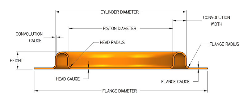
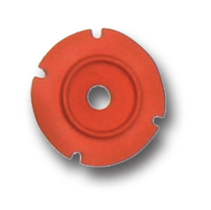
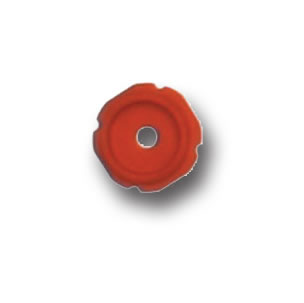
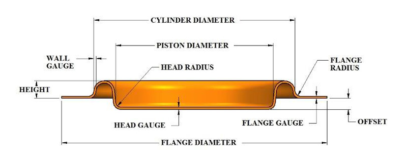
In this
style, the piston and the flange are molded on the same
plane. The benefit of this style is that the handwork
of forming the convolution is eliminated, which greatly
reduces the assembly time. This would be of importance
in high volume applications. The drawbacks to this type
of diaphragm are: a built-in spring rate, due to the molded-in
convolution, which must be considered during the design
stage, and a limited stroke-to-bore ratio. To improve
this ratio, an offset preconvoluted diaphragm can be designed
(see FC Offset figure at bottom of page). In this shape,
the piston head and flange are molded offset to each other,
thereby putting all the additional stroke capabilities
on one side of the convolution. This provides a longer
stroking diaphragm which still maintains the assembly
ease of a preconvoluted diaphragm.
Dimensions and Tolerances
Inches
mm
Inches
mm
Inches
mm
Inches
mm
Inches
mm
Cylinder Diameter
.25-.99
6-25
1.00-2.50
2-64
2.51-4.00
64-102
4.01-8.00
102-205
8.01 & up
205 & up
Height
See available sizes table
Cylinder
Diameter
Tolerances on Cylinder Diameter and Piston Diameter
are ± 0.010" per inch (0.254 mm) of
diameter but the tolerance will be no less than
± 0.010" (0.254 mm) or greater than
± 0.060" (1.52 mm)
Piston
Diameter
Head
& Flange Thickness
.015 ± .003
.038 ± 0.08
.017 ± .004
0.43 ± 0.10
.024 ± .004
0.61 ± 0.10
.035 ± .005
0.89 ± 0.13
.045 ± .007
1.14 ± 0.18
Wall
Gauge
.015 ± .003
.038 ± 0.08
.017 ± .003
0.43 ± 0.08
.024 ± .004
0.61 ± 0.10
.035 ± .005
0.89 ± 0.13
.045 ± .007
1.14 ± 0.18
Piston
& Flange Radius
.031
0.79
.063
1.60
.094
2.39
.125
3.15
.125
3.18
Flange
Diameter
Cyl. Diam. ± .750
Cyl. Diam. ± 19.05
Cyl. Diam. ± 1.000
Cyl. Diam. ± 25.40
Cyl. Diam. ± 1.500
Cyl. Diam. + 38.10
Cyl. Diam. ± 2.000
Cyl. Diam. ± 50.80
Cyl. Diam. ± 2.000
Cyl. Diam. ± 50.80
Diaphragm
Flange Diameter and Hole Trim Tolerance
Diameter
Size
Position
(Inches)
(mm)
(Inches)
(mm)
(Inches)
(mm)
0-1.00
.0-25.40
± .010
0.254
.010
0.254
1.01-3.00
25.65-76.20
± .020
0.508
.020
0.508
over 3.01
76.45
± .030
0.762
.030
0.762
Angular
Relationship of Holes: ± 1/2 Degree
Hole
Spacing for Type FC Diaphragms
Perforations
through the head or the flange should be located so that
there is at least 0.100 inches (2.54 mm) minimum between
the edges of holes. Also, holes should be located so that
there is at least 0.125 inches (3.175 mm) between the
edges of a hole and the trim periphery. It is also important
to arrange the hole pattern so that the radial distance
from the edge of the hole to the start of the blend radius
at either the piston head or cylinder clamp flange is
at least as far as indicated in the chart above.
Available Sizes
DiaCom
Part No.
Cylinder
Diameter
Piston
Diameter
Height
Gauge
Approx.
Convolution
Width
Effective
Pressure
Area
Maximum
Half-Stroke
(Inches)
(mm)
(Inches)
(mm)
(Inches)
(mm)
(Inches)
(mm)
(Inches)
(mm)
(Inches)
*
(Inches)
(mm)
FC-38-12
0.38
10
0.25
6
0.12
3
.013
0.33
.065
1.7
0.08
0.5
0.11
2.8
FC-51-08
0.50
13
0.13
8
0.08
2
.015
0.38
.095
2.4
0.13
0.8
0.01
0.3
FC-50-10
0.50
13
0.31
8
0.10
3
.020
0.51
.095
2.4
0.13
0.8
1.01
0.3
FC-50-10
0.50
13
0.38
10
0.10
3
.015
0.38
.060
1.5
0.15
1.0
0.07
1.8
FC-56-06
0.56
14
0.50
13
0.06
2
.016
0.41
.030
0.8
0.22
1.4
0.01
0.3
FC-62-07
0.62
16
0.44
11
0.07
2
.015
0.38
.090
2.3
0.22
1.4
0.04
1.0
FC-62-10
0.62
16
0.50
13
0.10
3
.015
0.38
.060
1.5
0.25
1.6
0.07
1.8
FC-71-15
0.71
18
0.53
13
0.16
4
.018
0.46
.090
2.3
0.30
1.9
0.10
2.5
FC-72-04
0.72
18
0.52
13
0.04
1
.015
0.38
.100
2.5
0.30
1.9
0.01
0.3
FC-72-09
0.72
18
0.52
13
0.09
2
0.15
0.38
.100
2.5
0.30
1.9
0.06
1.5
FC-75-15
0.75
19
0.45
11
0.15
4
.017
0.43
.150
3.8
0.28
1.8
0.03
0.8
FC-75-08
0.75
19
0.50
13
0.08
2
.017
0.43
.125
3.2
0.31
2.0
0.03
0.8
FC-75-10
0.75
19
0.62
16
0.10
3
.015
0.38
.065
1.7
0.37
2.4
0.07
1.8
FC-75-10
.075
19
0.63
16
0.10
3
.015
0.38
.060
1.5
0.37
2.4
0.07
1.8
FC-87-10
0.87
22
0.75
19
0.10
3
.015
0.38
.060
1.5
0.52
3.3
0.07
1.8
FC-88-10
0.88
22
0.66
17
0.10
3
.017
0.43
.110
2.8
0.47
3.0
0.01
0.3
FC-100-15
1.00
25
0.81
21
0.15
4
.017
0.43
.095
2.4
0.64
4.1
0.08
2.0
FC-100-15
1.00
25
0.81
21
0.15
4
.015
0.38
.095
2.4
0.64
4.1
0.08
2.0
FC-102-06
1.02
26
0.80
20
0.06
2
.008
0.20
.110
2.8
0.65
4.2
0.01
0.3
FC-106-06
1.06
27
0.94
24
0.06
2
.012
0.30
.060
1.5
.079
5.1
0.01
0.3
FC-107-12
1.07
27
0.82
21
0.12
3
.017
0.43
.125
3.2
0.70
4.5
0.01
0.3
FC-107-15
1.07
27
0.88
22
0.15
4
.013
0.33
.095
2.4
0.75
4.8
0.08
2.0
FC-116-15
1.16
29
0.98
25
0.15
4
.013
0.33
.090
2.3
0.90
5.8
0.08
2.0
FC-117-12
1.17
30
0.87
22
0.12
3
.020
0.51
.150
3.8
0.82
5.3
0.01
0.3
FC-118-18
1.18
30
0.91
23
0.18
5
.025
0.64
.135
3.4
0.86
5.5
0.01
0.3
FC-125-09
1.25
32
1.03
26
0.09
2
.017
0.43
.110
2.8
1.02
6.6
0.01
0.3
FC-125-15
1.25
32
1.06
27
0.15
4
.017
0.43
.095
2.4
1.05
6.8
0.08
2.0
FC-132-10
1.32
34
1.08
27
0.10
3
.020
0.51
.120
3.0
1.13
7.3
0.01
0.3
FC-137-15
1.37
35
1.19
30
0.15
4
.020
0.51
.090
2.3
1.29
8.3
0.08
2.0
FC-138-18
1.38
35
1.06
27
0.18
5
.025
0.64
.160
4.1
1.17
7.5
0.01
0.3
FC-150-12
1.50
38
0.94
24
0.13
3
.022
0.56
.280
7.1
1.17
7.5
0.01
0.3
FC-150-05
1.50
38
1.25
32
0.05
1
.010
0.25
.125
3.2
1.48
9.6
0.01
0.3
FC-150-15
1.50
38
1.31
33
0.15
4
.017
0.43
.095
2.4
1.55
10.0
0.08
2.0
FC-155-15
1.55
39
1.30
33
0.15
4
.020
0.51
.125
3.2
1.59
10.3
0.01
0.3
FC-160-09
1.60
41
1.33
34
0.09
2
.013
0.33
.135
3.4
1.68
10.9
0.01
0.3
FC-161-09
1.61
41
1.33
34
0.09
2
.020
0.51
.140
3.6
1.70
10.9
0.01
0.3
FC-162-15
1.62
41
1.44
37
0.15
4
.017
0.43
.090
2.3
1.84
11.9
0.08
.02
FC-163-09
1.63
41
1.44
37
0.09
2
.015
0.38
.095
2.4
1.85
11.9
0.01
0.3
FC-170-28
1.70
43
1.27
32
0.28
7
.030
0.76
.215
5.5
1.73
11.2
0.10
2.5
FC-173-09
1.73
44
1.50
38
0.09
2
.013
0.33
.115
2.9
2.05
13.2
0.01
0.3
FC-175-15
1.75
44
1.56
40
0.15
4
.013
0.33
.095
2.4
2.15
13.9
0.08
2.0
FC-199-12
1.99
51
1.54
39
0.12
3
.020
0.51
.225
5.7
2.45
15.8
0.01
0.3
FC-200-15
2.00
51
1.81
46
0.15
4
.017
0.43
.095
2.4
2.85
18.4
0.08
2.0
FC-212-12
2.12
54
1.88
48
0.12
3
.018
0.46
.120
3.0
3.14
20.3
0.04
1.0
FC-225-15
2.25
57
2.06
52
0.15
4
.017
0.43
.095
2.4
3.65
23.5
0.08
2.0
FC-250-15
2.50
64
2.31
59
0.15
4
.017
0.43
.095
2.4
4.54
29.3
0.08
2.0
FC-295-12
2.95
75
2.70
69
0.12
3
.017
0.43
.125
3.2
6.26
40.4
0.01
0.3
FC-300-25
3.00
76
2.69
68
0.25
6
.024
0.61
.155
3.9
6.35
41.0
0.15
3.8
FC-308-12
3.08
78
2.70
69
0.12
3
.017
0.43
.190
4.8
6.56
42.3
0.01
0.3
FC-325-12
3.25
83
3.00
76
0.12
3
.017
0.43
.125
3.2
7.67
49.5
0.01
0.3
FC-402-27
4.02
102
3.66
93
0.27
7
.035
0.89
.180
4.6
11.58
74.7
0.11
2.8
FC-425-37
4.25
108
3.75
95
0.37
9
.035
0.89
.250
6.4
12.56
81.0
0.24
6.1
FC-600-37
6.00
152
5.5
140
0.37
9
.035
0.89
.250
6.4
25.95
167.4
0.24
6.1
FC-1150-50
11.50
292
11.00
279
0.50
13
.045
1.14
.250
6.4
99.35
641.0
0.37
9.4
*Metric effective pressure
area shown in square centimeters.