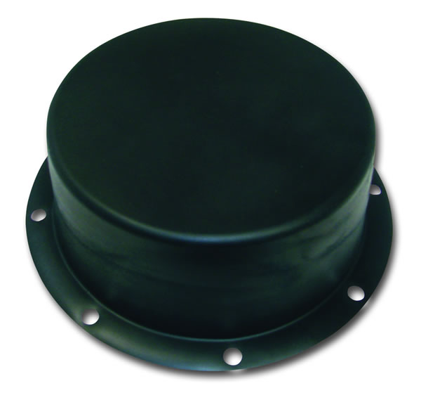
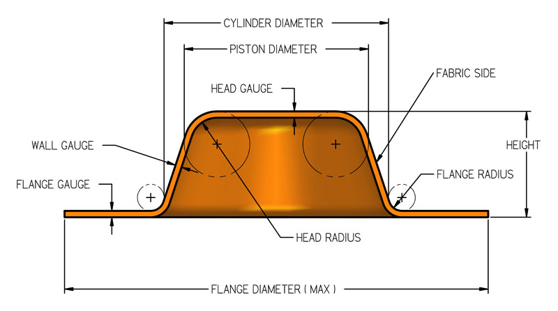
The
Type F is commonly referred to as the top hat
diaphragm. It exhibits all of the benefits that are associated
with rolling diaphragms. These diaphragms have the longest
stroke-to-bore ratio, zero spring rate, no breakaway friction,
constant effective pressure area, and long life. Some
of the drawbacks to Type F diaphragms are additional assembly
time required when inverting the top head corner radius
during installation, and an inability to withstand reverse
pressure.
The flange of the Type F diaphragm is designed to seal
like a gasket between the two flat surfaces of the cylinder
and bonnet. The outside edge and bolt holes can be cut
into any configuration desired. An effective seal should
be obtained by compressing the flange area 20-25% thickness.
To extend cycle life and reduce four-cornering
of the diaphragm, a double taper design may be utilized
(see Figure 1). This design reduces the diameter of the
bottom end of the diaphragm which minimizes excess material
in this area and relieves circumferential compressive
stress.
Dimensions and Tolerances
Inches
mm
Inches
mm
Inches
mm
Inches
mm
Inches
mm
Cylinder Diameter
.25-.99
6-25
1.00-2.50
25-64
2.51-4.00
64-102
4.01-8.00
102-205
8.01 & up
205 & up
Height
See available sizes table
Cylinder
Diameter
Tolerances on Cylinder Diameter and Piston Diameter
are ± 0.010" per inch (0.254 mm) of
diameter but the tolerance will be no less than
± 0.010" (0.254 mm) or greater than
± 0.060" (1.52 mm)
Piston
Diameter
Head
& Flange Thickness
.015 ± .003
0.38 ± .08
.017 ± .004
0.43 ± 0.10
.024 ± .004
0.61 ± .10
.035 ± .005
0.89 ± 0.13
.045 ± .007
1.14 ± 0.18
Wall
Gauge
.015 ± .003
0.38 ± 0.08
.017 ± .004
0.43 ± 0.08
.024 ± .004
0.61 ± 0.10
.035 ± .005
0.89 ± 0.13
.045 ± .007
1.14 ± 0.18
Piston
Radius
.094
1.39
.125
3.18
.156
3.96
.250
6.35
.250
6.35
Flange
Radius
.031
0.79
.063
1.60
.094
2.39
.125
3.18
.125
3.18
Flange
Diameter
Cyl. Diam. ± .750
Cyl. Diam. ± 19.05
Cyl. Diam. ± 1.000
Cyl. Diam. ± 25.40
Cyl. Diam. ± 1.500
Cyl. Diam. + 38.10
Cyl. Diam. ± 2.000
Cyl. Diam. ± 50.80
Cyl. Diam. ± 2.000
Cyl. Diam. ± 50.80
Diaphragm
Flange Diameter and Hole Trim Tolerance
Diameter
Size
Position
(Inches)
(mm)
(Inches)
(mm)
(Inches)
(mm)
0-1.00
.0-25.40
± .010
0.25
.010
0.25
1.01-3.00
25.65-76.20
± .020
0.51
.020
0.51
over 3.01
76.45
± .030
0.76
.030
0.76
Hole
Spacing for Type F Diaphragms
Max.
Working Pressure (P.S.I.)/KPA
(0-50)
0-350
(51-150)
357-1050
(151-300)
1057-2100
(301-500)
2107-3500
Seal
Area Minimum Inches/mm
.100
2.54
.150
3.81
.200
5.08
.250
6.35
Hole Spacing
Perforations
through the head or the flange should be located so that
there is at least 0.100 inches (2.54 mm) minimum between
the edges of holes. Also, holes should be located so that
there is at least 0.125 inches (3.175 mm) between the
edges of a hole and the trim periphery. It is also important
to arrange the hole pattern so that the radial distance
from the edge of the hole to the start of the blend radius
at either the piston head or cylinder clamp flange is
at least as far as indicated in the chart above.