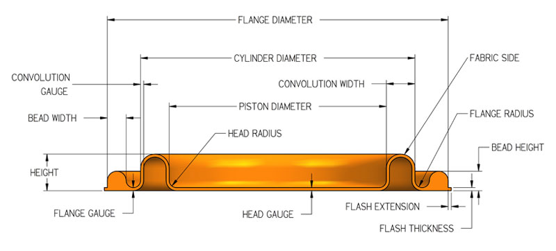
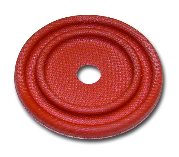
This
style diaphragm is similar in function to the Type
FC diaphragm, while the sealing and hardware designs
are the same as the Type
D.
Dimensions and Tolerances
Inches
mm
Inches
mm
Inches
mm
Inches
mm
Inches
mm
Cylinder Diameter
.37-.99
9-25
1.00-2.50
25-64
2.51-4.00
64-102
4.01-8.00
102-205
8.01 & up
205 & up
Height
See available sizes table
Cylinder
Diameter
Tolerances on Cylinder Diameter and Piston Diameter
are ± 0.010 per inch (0.254 mm) of diameter
but the tolerance will be no less than ±
0.010 (0.254 mm) or greater than ± 0.060
(1.52 mm)
Piston
Diameter
Head
& Flange Thickness
.015 ± .003
0.38 ± 0.08
.017 ± .004
0.43 ± 0.10
.024 ± .004
0.61 ± 0.10
.035 ± .005
0.89 ± 0.13
.045 ± .007
1.14 ± 0.18
Wall
Gauge
.015 ± .003
0.38 ± 0.08
0.17 ± .004
0.43 ± 0.08
.024 ± .004
0.61 ± 0.10
.035 ± .005
0.89 ± 0.13
.045 ± .007
1.14 ± 0.18
Flash
Projection
.025 Max.
0.64 Max.
.025 Max.
0.64 Max.
.035 Max.
0.89 Max.
.040 Max.
1.02 Max.
.056 Max.
1.42 Max.
Flash
Thickness
.025 Max.
0.64 Max.
.025 Max.
0.64 Max.
.035 Max.
0.89 Max.
.040 Max.
1.02 Max.
.056 Max.
1.42 Max.
Piston/Flange
Radius
.031
.075 Max
.063
1.60 Max
.094
2.39
.125
3.18
.125
3.18
Flange
Diameter
Cyl. Diam. + .313
Cyl. Diam. + 7.95
Cyl. Diam. + .500
Cyl. Diam. + .12.70
Cyl. Diam. + .750
Cyl. Diam. + 19.50
Cyl. Diam. + 1.000
Cyl. Diam. + 25.40
Cyl. Diam. + 1.000
Cyl. Diam. + 25.40
Bead
Width
.094 ± .003
2.39 ± 0.08
.125 ± .003
3.18 ± 0.08
.187 ± .003
4.75 ± 0.08
.250 ± .003
6.35 ± 0.08
.250 ± .004
6.35 ± 0.10
Bead
Height
.095 ± .004
2.41 ± 0.10
.135 ± .004
3.43 ± 0.10
.200 ± .005
5.08 ± 0.13
.270 ± .006
6.86 ± 0.15
.270 ± .008
6.86 ± 0.20
Diaphragm
Flange Diameter and Hole Trim Tolerance
Diameter
Size
Position
(Inches)
(mm)
(Inches)
(mm)
(Inches)
(mm)
0-1.00
.0-25.40
± .010
0.25
.010
0.25
1.01-3.00
25.65-76.20
± .020
0.51
.020
0.51
over 3.01
over 76.45
± .030
0.76
.030
0.76
Angular Relationship of holes: ±
1/2 degree.
Hardware
Recommendations
Cylinder Diameter
.25-.99
6-25
1.00-2.50
25-64
2.51-4.00
64-102
4.01-8.00
102-205
8.01 & up
205 & up
Groove Width
.109
2.77
.141
3.58
.219
5.56
.281
7.14
.281
7.14
± .003
0.08 ±
Groove Height
.076
1.93
.105
2.67
.160
4.06
.224
5.69
.224
5.69
± .002
0.05 ±
Flange & Piston Corner Radii
.031
0.79
.063
1.60
.094
2.39
.125
3.18
.125
3.18
Lip Width
.062
1.57
.125
3.18
.187
4.75
.250
6.35
.250
6.35
± .003
0.08 ±
Lip Clearance
.021
0.53
.021
0.53
.031
0.79
.036
0.91
.048
1.22
± .003
0.08 ±
Available Sizes
DiaCom
Part No.
Cylinder
Diameter
Piston
Diameter
Height
Gauge
Approx.
Convolution
Width
Effective
Pressure
Area
Maximum
Half-Stroke
(Inches)
(mm)
(Inches)
(mm)
(Inches)
(mm)
(Inches)
(mm)
(Inches)
(mm)
(Inches)
*
(Inches)
(mm)
DC-37-12
0.37
9
0.27
7
0.12
3
.017
0.43
.050
1.3
0.08
0.5
0.11
2.8
DC-62-10
0.62
16
0.50
13
0.10
3
.020
0.51
.060
1.5
0.25
1.6
0.07
1.8
DC-69-12
0.69
18
0.50
13
0.12
3
.017
0.43
.095
2.4
0.28
1.8
0.05
1.3
DC-91-15
0.91
23
0.72
18
0.15
4
.020
0.51
.095
2.4
0.52
3.4
0.01
0.3
DC-125-15
1.25
32
1.05
27
0.15
4
.017
0.43
.100
2.5
1.04
6.7
0.08
2.0
DC-150-15
1.50
38
1.31
33
0.15
4
.017
0.43
.095
2.4
1.55
10.0
0.08
2.0
DC-175-15
1.75
44
1.56
40
0.15
4
.017
0.43
.095
2.4
2.15
13.9
0.08
2.0
*Metric effective pressure
area shown in square centimeters.